Related Posts

Elevators Market
News, Technical, Event, Spart Part Of Elevators And Escalator
News, Technical, Event, Spart Part Of Elevators And Escalator

The preceding brief discussion of early elevator history introduced the traction-type elevator. The first high-rise application of this type of elevator was in the Beaver Building in New York City in 1903, followed by such notable installations as the Singer Building (demolished in 1972) and the Woolworth Building. These elevators were of the gearless traction type that is at present the accepted standard for the high-rise, high-speed [over 400 fpm (2.0 mps)], and high-quality elevator installation.
The gearless traction elevator consists of a large, slow-speed (50 to 200 rpm) dc motor of four to eight poles directly connected to a drive sheave of about 30 to 48 in. (750 to 1200 mm) in diameter. An electrically released, spring-applied brake is arranged to apply stopping to the drive sheave. Slow-speed dc motors and ac motors (being introduced), though expensive and massive, are necessary to maintain the necessary torque to directly drive large-diameter sheaves. The larger-diameter sheaves also conform to the bending radius of elevator steel ropes. A limitation is imposed by safety codes as good practice for long rope life and is generally established at a minimum of 40 times the diameter of the wire rope used. For example, a 1/2-in. (13-mm) wire rope would require a minimum sheave size of 20 in. (500 mm).
The slow speed of the direct drive gearless traction machine is necessitated by the speed of the elevator it serves. For example, for a 500 fpm (2.5 mps) elevator and a sheave diameter of 30 in. (750 mm), a top speed of 86 rpm is required. To level this elevator to a landing at a maximum speed of 25 fpm (0.125 mps), 4.3 rpm is necessary. Gearing with higher-speed motors has been introduced by at least one major manufacturer to gain these higher speeds. The continuous operation of elevators [up to 25,000 mi (40,000 km) per year] and the relative ease of maintenance of the gearless machines, as well as their dependability, make them the preferred type for higher speeds.
On higher-speed gearless traction machines of 800 fpm (4.0 mps) or more, the double- wrap principle is generally applied to obtain traction and to minimize rope wear. The ropes from the car are wrapped around the drive sheave, around a secondary or idler sheave, around the drive sheave, and down to the counterweight as seen in the figure below.
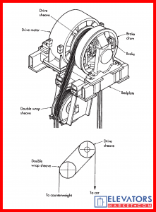
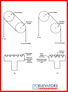
The groove seats are round, providing support on the full half of the rope, thus eliminating pinching action and minimizing wear. Traction is obtained by the pressure of the ropes on the sheave. As may be noted, increasing the weight on the car or counterweight increases the force so that friction between the ropes and the sheave increases traction.
Elevator machines are also roped with a single-wrap arrangement, which is applied to both gearless and geared machines. The single-wrap arrangement provides traction by the use of grooves that will pinch the ropes with varying degrees of pressure depending on the shape of the groove and its undercutting. The most effective single-wrap arrangement provides 180 degrees of rope contact with the sheave without a deflecting sheave, as shown in Figure below (for single-wrap traction [SWT], 2:1 roping).
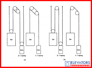
Conventional elevators are roped either 1:1 or 2:1 for both car and counterweight. In some unusual installations and special applications, 1:1 car and 2:1 counterweight roping has been used. In that event the counterweight must be at least twice as heavy as the weight of the car. The 1:1 arrangement is the most popular for higher speeds and has been used for a load and speed of 10,000 lb (4500 kg) at 1600 fpm (8 mps). The 2:1 arrangement allows the use of a higher-speed, and therefore a smaller but faster, elevator. The mechanical advantage of 2:1 roping requires that only half the weight be lifted, so 2:1 is generally used whenever loads in excess of 4000 lb (1600 kg) must be lifted. The economy of the faster motor, which can be built smaller and lighter than lower-speed dc motors, also makes 2:1 roping attractive for a full range of speed requirements from 100 to 700 fpm (0.5 to 3.5 mps) or more and for any lifting capacity.
Any of the aforementioned 1:1 and 2:1 roping arrangements can be provided with the elevator machine in the basement or at a lower level. The appropriate sheaves are installed in the overhead space to direct the ropes from the machine to the car and counterweight. The preferred arrangement is the single-wrap traction type. A foundation must be provided for the machine that will overcome the uplift and solidly anchor the machine under all conditions of operation and safety application.
The long life, smoothness, and high horsepower of gearless traction elevators provide a durable elevator service that can outlive the building itself. The original gearless machines in the Woolworth Building were reused when that building’s elevators were modernized in 1950, again in 1970, and for a third time in 1990. The gearless machine not only provides speed, if necessary, but is also capable of the performance essential to any well-elevatored building.
Essential to elevatoring considerations is the requirement that a gearless traction machine, no matter what its lifting capacity or speed, must be capable of optimum floor-to-floor operating time commensurate with passenger comfort. Stated another way, the machine must be capable of starting a filled elevator car, accelerating to a maximum speed for the distance traveled, and slowing to a stop in a minimum time of about 4.5 to 5.0 sec. This must be performed under all conditions of loading, either up or down. The elevator system must be so arranged that such acceleration and deceleration take place without discomfort to the passenger from a too rapid change in the rate of acceleration or decel- eration (with optimum jerk). Furthermore, the elevator must be capable of releveling, while passenger load is changing at a floor (correcting for rope stretch), with almost imperceptible movement.
The Next Article Will Be About Geared Traction Machine.
Stay Connected And Never Forget Safty First


