Related Posts

Elevators Market
News, Technical, Event, Spart Part Of Elevators And Escalator
News, Technical, Event, Spart Part Of Elevators And Escalator

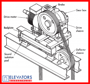
As the name implies, the geared traction elevator machine utilizes a reduction gear with a high-speed motor to drive the traction sheave. A high-speed ac or dc motor drives a worm and gear reduction unit, which in turn drives the hoisting sheave, the net result being the slow sheave speed and high torque necessary for elevator work. A brake is applied by spring to stop the elevator and/or hold the car at a floor level. Recent (1990s) introductions have been planetary gearing and helical gearing to replace the traditional worm gear approach.
The geared traction machine is used for elevators and dumbwaiters of all capacities from 25 to 30,000 lb (10 to 14,000 kg) or more, and speeds from 25 to 450 fpm (0.125 to 2.3 mps). The complete flexibility of worm gear ratios and motor speeds and horsepowers, as well as drive sheave diameters and roping arrangements (1:1, 2:1, and, sometimes, 3:1), makes this vast range of application practical. In some materials-handling applications, geared machines are used for speeds of 600 fpm or more (3.0 mps) with excellent results.
The geared traction elevator is an outgrowth of the earlier drum-type elevators. The steam engine gave way to the electric motor and gear as show in figure below:
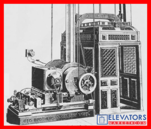 |
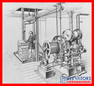 |
And the drum gave way to the drive sheave:
 |
 |
The grooved drive sheave was an outgrowth of the traction principle applied to gearless elevators; instead of ropes being wrapped around the sheave, grooves were cut into the sheave and the necessary friction was created by the pinching action of the grooves on the rope . Various types of grooving are used for different loads and traction requirements. Generally, the sharper the undercut angle, the greater the traction (and, usually, the greater rope and sheave wear).
Polyurethane groove liners capable of providing greater traction and less rope wear are being used by at least one manufacturer.
Geared machines have been driven by either one-speed or two-speed ac motors, by dc motors utilizing the Ward-Leonard means of control, or by ac or dc motors with SCR, VVVF, or other solid-state control. Ac motor machines are often used for speeds from 25 to 150 fpm (0.125 to 0.75 mps) with single- or two-speed motors or with solid-state drives to 450 fpm (2.25 mps). Stopping with single-speed motors is accomplished by disconnecting the power from the motor and stopping the car by a combination of slide and brake action. Two-speed ac operation employs a double-wound motor, a fast-speed winding for full-speed running, and a slow-speed winding (which can be any ratio as high as 6:1, i.e., the slow speed being 1/6 full speed) for stopping, leveling, and, if required, releveling. Operation is generally to start at full speed, run, switch to low speed at a measured distance from the stop, and accomplish the final stop by a combination of brake and slide. The floor-level accuracy of plus or minus 1/2 to 1 in. (13 to 24 mm) can be obtained under all conditions of load, as contrasted with one-speed accuracy of 1 to 3 in. (24 to 75 mm), which will vary with load. Much greater accuracy can be obtained when solid-state ac motor drives are employed, and various upgrades can be retrofitted to existing single-speed elevators. In contrast, the dc Ward-Leonard drive or a solid-state motor drive allows the car to be stopped electrically before the brake is applied, resulting in leveling accuracy from 1/4 to 1/2 in. (6 to 13 mm) under all conditions of load, and much softer stops than produced by the ac machine.
With either ac or dc geared elevators, the floor-to-floor performance can be established, which is essential in calculations in estimating the numbers of elevators for a particular building.


